
26 Ağustos 2010 Perşembe
21 Temmuz 2010 Çarşamba
First Pictures - Patrick Is Born
And Voila! Here is the final thing.


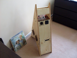
 Take it easy Patrick, take it easy.
The LP's and the bass are placed in the picture to help viewers get a better idea of the actual size. The height of the cabin is 95 cm and fits nicely into the trunk of a small car. The weight is 22 kg.


The LP's and the bass are placed in the picture to help viewers get a better idea of the actual size. The height of the cabin is 95 cm and fits nicely into the trunk of a small car. The weight is 22 kg.
Control Panel
Here is the control panel of Patrick designed by Mert F. Torgay. Thanks to him for his time and efforts.
 The Error LED's are directly taken from the Tripath Amplifier. The mute/protection LED which is located as the first Error LED serves as a very good indicator of amplifier condition. It lights up whenever the amplifier shuts down for protection so if the batteries are depleted or the limiter kicks in, this LED is on.

Measurements and Crossover Design
Measurements
For the measurements, I wrote a simple code in Matlab. Using the code, the computer outputs a steady sine or sweep and takes input from the sound card or user prompt. With the help of this I could measure frequency response and other stuff like impedance, output voltage etc. Here is a piece of the code for frequency measurement where sound card input and outputs are utilized:
There are lots of things to add to the code (e.g. windowing, calibration, octave averaging) but it helps me quite well as it is.
The Crossover
Patrick has second order crossovers for the mid-bass speakers and the tweeter. The bandpass section has a first order low-pass filter, the side-fills have a first order high-pass filter.
The second order crossovers were intended to be in Linkwitz-Riley alignment because the speakers on the cabin are placed quite away from each other and problems with phase matching is expected. Linkwitz-Riley alignment is regarded as the alignment least sensitive to loudspeaker placement because of the -6dB crossover point. But because the Linkwitz-Riley alignment required some very large size capacitors, I decided to use Butterworth filters with distant cut-off frequencies. This wasn't as flat or as coherent as the Linkwitz-Riley alignment but I thought I could spare some from the mid frequencies.
The final responses, measured from three different points in the vertical axis are in the graphs below. Those three points were selected so that each has a 120° phase angle difference from the previous one at crossover point.

The red-green one is the reference where two speakers are exactly in phase. This one translates to a few degrees up in the vertical axis which is the usual listening angle when Patrick is on the ground and people are standing up or sitting down in far field. To account for the poor high frequency dispersion of the tweeter a little extra gain was added using the tone controls. This helps for a more neutral response overall in open field. The effects of this gain is clearly visible above 8kHz.
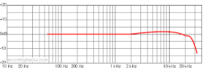
Please note that the graphs above were measured using a Behringer ECM8000 microphone. This is not a very high quality microphone. Unfortunately I couldn't lay my hands on a proper microphone this time. Anyway, the measurements were done from near field with high level signals so noise was not an issue. The unflat frequency response of the microphone, on the other hand, should always be taken into account during measurements.
For the measurements, I wrote a simple code in Matlab. Using the code, the computer outputs a steady sine or sweep and takes input from the sound card or user prompt. With the help of this I could measure frequency response and other stuff like impedance, output voltage etc. Here is a piece of the code for frequency measurement where sound card input and outputs are utilized:
for measureno=1:3
N=48000;
T=10;
A=0.1;
f1=500;
f2=20000;
%generate sine with function "generatesine"
[signal,freqArray,tArray,signalwpre]=generatesine(f1,f2,N,T,1,1);
pause
%apply amplitude and plot!
signal=A.*signal;
signalwpre=A.*signalwpre;
plot(signalwpre)
%%do the recording
ai=analoginput('winsound');
mikrofon=addchannel(ai,1);
set(ai,'SampleRate',N);
set(ai,'SamplesPerTrigger',T*N);
set(ai,'TriggerChannel',mikrofon)
set(ai,'TriggerType','Software')
set(ai,'TriggerCondition','Rising')
set(ai,'TriggerConditionValue',0.01)
set(ai,'TriggerDelayUnits','Seconds')
set(ai,'TriggerDelay',0.5)
ao = analogoutput('winsound');
addchannel(ao,1:2);
set(ao,'SampleRate',N)
putdata(ao,[signalwpre' signalwpre'])
start(ao)
start(ai);
wait(ai,T+4);
stop(ao);
[rec,time] = getdata(ai);
plot(rec)
%for test purposes only
%rec=signal;
if max(rec)>=1
warning('ADC clip etti sanki')
elseif max(rec)<0.1
warning('Seviye çok düşük bebeğim')
end
%%do the fourier transform--dB value has no reference
cp=2/length(rec).*fft(rec*10^8);
cw=(abs(cp.^1)).^2;
%plot cw to SPL with smoothing
cw=smooth(cw,200*T-1);
Lw=10*log10(cw);
SPL(:,measureno)=abs(Lw);
freq=(1:length(cw))/T-1;
semilogx(freq,SPL);
delete(ao)
end
AXIS([f1 f2 max(max(SPL))-40 max(max(SPL))+10])
There are lots of things to add to the code (e.g. windowing, calibration, octave averaging) but it helps me quite well as it is.
The Crossover
Patrick has second order crossovers for the mid-bass speakers and the tweeter. The bandpass section has a first order low-pass filter, the side-fills have a first order high-pass filter.
The second order crossovers were intended to be in Linkwitz-Riley alignment because the speakers on the cabin are placed quite away from each other and problems with phase matching is expected. Linkwitz-Riley alignment is regarded as the alignment least sensitive to loudspeaker placement because of the -6dB crossover point. But because the Linkwitz-Riley alignment required some very large size capacitors, I decided to use Butterworth filters with distant cut-off frequencies. This wasn't as flat or as coherent as the Linkwitz-Riley alignment but I thought I could spare some from the mid frequencies.
The final responses, measured from three different points in the vertical axis are in the graphs below. Those three points were selected so that each has a 120° phase angle difference from the previous one at crossover point.

Patrick's Frequency Response
Please note that the graphs above were measured using a Behringer ECM8000 microphone. This is not a very high quality microphone. Unfortunately I couldn't lay my hands on a proper microphone this time. Anyway, the measurements were done from near field with high level signals so noise was not an issue. The unflat frequency response of the microphone, on the other hand, should always be taken into account during measurements.

Frequency Response of My Measurement Microphone

Response And Power Handling In Low Frequencies
The low frequency section was modelled using Unibox loudspeaker box modelling spreadsheet. This is a complete tool for low frequency cabin design. Below are the final responses. I have added the results of the two low frequency sections using Excel, one in phase and one 90° off-phase. After setting up the speaker, I have matched phase by measuring output of both sections at the crossover frequency. They have matched pretty well (better than 30°) at crossover frequency after reversing the phase of the bandpass section. So the final response is expected to be similar to the curve with Theta=0 sum.

Low Frequency Response of Patrick Modelled With Unibox
This graph also shows maximum power handling of Patrick. The results shown are maximum attainable SPL values limited by driver excursion in the bandpass section.
The tone controls have been tuned to have a similar rise with the curves shown above so that reducing the bass level using the tone controls, a flat response is attained. This way, the loudspeaker is fit for use indoors and outdoors in open field equally. I leave the bass control at -3dB in open field which works quite well.
20 Temmuz 2010 Salı
The Body of Patrick
The Cabinet
The loudspeaker cabin has 4 sections.
1-Closed chamber for bandpass speakers
2-Ported chamber for bandpass speakers and battery housing
3-Closed chamber for mid-bass speakers
4-Vented (vented for cooling) chamber for electronics and high frequency drivers.

To make the cabin a little lighter, I didn't use MDF this time. I bought some quality plywood for the cabin. The front and rear faces are 18mm thick plywood. All other places I used 12mm thick plywood.
First of all, the panels were cut using CNC and then were assembled by Mr. Orhan, an enthusiastic and very skilled carpenter.


When it was over, we put the cabin under torture and waited for a day (those grips are called "torture" in Turkish).

The loudspeaker cabin has 4 sections.
1-Closed chamber for bandpass speakers
2-Ported chamber for bandpass speakers and battery housing
3-Closed chamber for mid-bass speakers
4-Vented (vented for cooling) chamber for electronics and high frequency drivers.

Transparent Model Rendered With Solidworks
To make the cabin a little lighter, I didn't use MDF this time. I bought some quality plywood for the cabin. The front and rear faces are 18mm thick plywood. All other places I used 12mm thick plywood.
Construction
We got very lucky with construction this time. Mert F. Torgay, a close friend of mine, was working in an architectural design office which had its own workshop. We took the sketches and wood panels there and began the construction.First of all, the panels were cut using CNC and then were assembled by Mr. Orhan, an enthusiastic and very skilled carpenter.


When it was over, we put the cabin under torture and waited for a day (those grips are called "torture" in Turkish).

Cabin Geometry
First Ideas
As I have said before, the concept had occurred to me while I was in the army. Then I had some simple ideas for the cabin. It would be look like a traditional cuboid loudspeaker but also have wheels. This wasn't very interesting or functional, so I asked a few friends that they contribute some ideas for the cabin. Arda Halu, who is an occasional caricaturist came up with the winning idea.

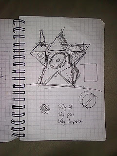
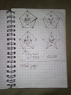
Here are the sketches on my notebook, drawn by Arda and myself:


Now it was decided that we go for a star shaped loudspeaker. Then we named it as well, "Patrick". This was a reference to the Spongebob Squarepants character Patrick Star. Now we were ready for a model. I began studies in Solidworks.


As I have said before, the concept had occurred to me while I was in the army. Then I had some simple ideas for the cabin. It would be look like a traditional cuboid loudspeaker but also have wheels. This wasn't very interesting or functional, so I asked a few friends that they contribute some ideas for the cabin. Arda Halu, who is an occasional caricaturist came up with the winning idea.

Arda Halu
Here are the sketches on my notebook, drawn by Arda and myself:


Sketching the "Star" With Mert F. Torgay
Now it was decided that we go for a star shaped loudspeaker. Then we named it as well, "Patrick". This was a reference to the Spongebob Squarepants character Patrick Star. Now we were ready for a model. I began studies in Solidworks.

Patrick Star
Solidworks Model
Using Solidworks, I drew all parts of the speaker one by one and created an assembly. First I determined the sizes of the acoustic chambers. There would be three acoustic chambers with a total volume of 25 liters. Using this information I optimized the size of the cabin and studied on the details of wooden construction. When this was done, it felt like the speaker was almost finished.

Solidworks Model
17 Temmuz 2010 Cumartesi
Loudspeakers (At Last)
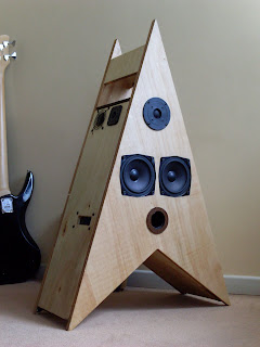
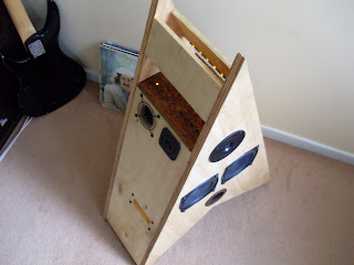
Patrick, as I may have mentioned before, is a hi-fi mono speaker with very wide coverage angles. Patrick has a bandpass subwoofer section, a closed box mid-bass section, a silk dome tweeter and 2 side-fills.
The Bandpass Section - A Small Subwoofer
The bandpass is built using two Vifa P13WH-00-08's connected in parallel. These drivers were presents from Onur İlkorur. Thanks to him for this nice gift.
The output level of the bandpass section is 99dBSPL between 45Hz and 110Hz (-3dB). It could have been louder but because the drivers I had were small 5" drivers and too much excursion is required for this frequency span the output had to be limited. Anyway, the output is enough to accompany the other drivers on the system and power usage is in a sensible 20 watts maximum.
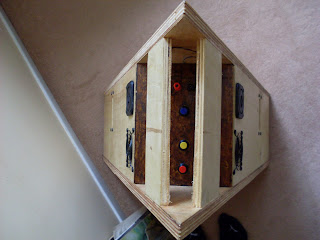
Luckily, I could have thought adding a "window" to the bandpass ported chamber to see what the speakers are doing. Here is a picture taken from the window looking inside. Top right is the port, on the left are the batteries of Patrick and if you look carefully you can see 3 speakers all of which belong to the bandpass section. One is the left speaker (obvious large one on the picture), one is the image of the right speaker on the battery (top left) and the other is the right speaker itself (only a part of the surround is seen). So, the bandpass section has two actual speakers.

What Is A Bandpass?
A bandpass speaker is a type of low frequency enclosure design. It is the combination of a closed-box and a vented-box speaker.

As you see, the loudspeaker unit sees a closed chamber at one side and a ported chamber at the other. The closed chamber traps the out of phase energy emitted from the rear side of the speaker cone and adjusts speaker's damping ratio while the ported section blows like a whistle on the tuned frequency band. This is the kind of speaker you find on PC sound systems. If your 2.1 or 5.1 PC speaker came with a box which does not have a visible speaker on it but provides high levels of low frequency sound, it is a bandpass speaker. Bandpasses are not hi-fi. They are too slow for hi-fi. They lack definition in transients and blur the audio content. But to get the maximum sound, there's nothing like them. Just like a huge whistle.
The Mid-Bass Section
The mid-bass section uses two 5" speakers serially connected. These are -to my surprise- well-built speakers manufactured by Nokia. They must be old, because the label says "Made in Western Germany". These speakers have light cones and small motors but sound very balanced. The model number is LPT 130/19/135.

The mid-bass section is a closed box design. This means the speakers are stuck on a chamber which has no leakage to the exterior or another chamber. It was the design of choice in this project because I do not need the speaker to work on below resonance frequencies. This keeps the design simple and limits driver excursion.
High Frequency Drivers
The tweeter is a Westra 25mm silk dome model. It's model number is -- I forgot to note that--. It sounds and measures quite well. With the help of the eq on the preamp, high frequency content above 8kHz is a little supported and the outcome is even better.
Patrick also has two sidefills, these are tiny speakers to increase sound intensity on sides of the cabin. They have a flat response about 8dB below the main speakers. To serve as a side-fill, a first order high-pass filter was added. With the help of this, the overall sound energy of the speaker is a little more balanced.
The Bandpass Section - A Small Subwoofer
The bandpass is built using two Vifa P13WH-00-08's connected in parallel. These drivers were presents from Onur İlkorur. Thanks to him for this nice gift.
The output level of the bandpass section is 99dBSPL between 45Hz and 110Hz (-3dB). It could have been louder but because the drivers I had were small 5" drivers and too much excursion is required for this frequency span the output had to be limited. Anyway, the output is enough to accompany the other drivers on the system and power usage is in a sensible 20 watts maximum.
Luckily, I could have thought adding a "window" to the bandpass ported chamber to see what the speakers are doing. Here is a picture taken from the window looking inside. Top right is the port, on the left are the batteries of Patrick and if you look carefully you can see 3 speakers all of which belong to the bandpass section. One is the left speaker (obvious large one on the picture), one is the image of the right speaker on the battery (top left) and the other is the right speaker itself (only a part of the surround is seen). So, the bandpass section has two actual speakers.

Inside The Bandpass Chamber of Patrick
What Is A Bandpass?
A bandpass speaker is a type of low frequency enclosure design. It is the combination of a closed-box and a vented-box speaker.
As you see, the loudspeaker unit sees a closed chamber at one side and a ported chamber at the other. The closed chamber traps the out of phase energy emitted from the rear side of the speaker cone and adjusts speaker's damping ratio while the ported section blows like a whistle on the tuned frequency band. This is the kind of speaker you find on PC sound systems. If your 2.1 or 5.1 PC speaker came with a box which does not have a visible speaker on it but provides high levels of low frequency sound, it is a bandpass speaker. Bandpasses are not hi-fi. They are too slow for hi-fi. They lack definition in transients and blur the audio content. But to get the maximum sound, there's nothing like them. Just like a huge whistle.
The Mid-Bass Section
The mid-bass section uses two 5" speakers serially connected. These are -to my surprise- well-built speakers manufactured by Nokia. They must be old, because the label says "Made in Western Germany". These speakers have light cones and small motors but sound very balanced. The model number is LPT 130/19/135.

Nokia Mid-Bass Drivers
The mid-bass section is a closed box design. This means the speakers are stuck on a chamber which has no leakage to the exterior or another chamber. It was the design of choice in this project because I do not need the speaker to work on below resonance frequencies. This keeps the design simple and limits driver excursion.
High Frequency Drivers
The tweeter is a Westra 25mm silk dome model. It's model number is -- I forgot to note that--. It sounds and measures quite well. With the help of the eq on the preamp, high frequency content above 8kHz is a little supported and the outcome is even better.
Patrick also has two sidefills, these are tiny speakers to increase sound intensity on sides of the cabin. They have a flat response about 8dB below the main speakers. To serve as a side-fill, a first order high-pass filter was added. With the help of this, the overall sound energy of the speaker is a little more balanced.
8 Temmuz 2010 Perşembe
Schematics and Built Electronics
Schematics For The Preamplifier

This is the preamplifier section. At the top left, there is a voltage divider to create a virtual ground for the opamps. Down on the left is the input and downmix of stereo channels to mono. After a buffer, the signal is sent to the tone control section and then output with another buffer section. The input and output buffer sections apply 8 dB of gain each.
Schematics For The Power Management Section
Power management is a strong name, but this is exactly what this circuit is doing.
The circuit has a DC input, battery connections, LED outputs for power and charging, a charger circuit and relays for routing.

On the first tests the relay no.3 (output relay) was fried because it was connecting a full capacitor to the empty capacitors at the amplifier board input and this drew enormous current. I solved this problem by reducing the 2200micF cap with a smaller one and installing a better (8 ampere) relay. Now it works more reliably.
Built Electronics
This is the electronics section built on an aluminum board which also serves as the heatsink for the amplifier. At the top is the power management and bottom left is the preamplifier. Bottom right is the amplifier and limiter/DC regulator on top of each other. All of the electronics of Patrick are right here. This piece goes where the larynx of Patrick would be located.

The Electronics Board
Limiter and Other Utilities
Limiter
When I realized that an efficient bandpass design with the woofers I had had a working frequency at about 120 Hz, I knew I would need lots of displacement for the 40 Hz I had aimed. To go all the way down to 40 Hz, the bandpass ported chamber frequency is set to 74 Hz, which is almost an octave lower than the 120Hz. With this setup, the woofers need 4mm of displacement at around 18 watts, 45Hz. It is quite inefficient and can't handle lots of power, but I do not have much space and don't want to order new speakers. There aren't many speaker distributors in Turkey and shipping from other countries is pricey.
Seeing the great displacement requirements and considering volume levels and inputs may be easily misused by careless party goers, I decided to build some kind of protection for the bandpass drivers.

This simple circuit takes the loudspeaker output, applies a low-pass filter and rectifies the output of this filter to drive a muting relay. The low-pass frequency is set at 45Hz. This is the bottom working frequency of the ported chamber and below this frequency displacement rises rapidly. The use of a relay seems inappropriate in such an active circuit but it was an easy design and I had all the materials so I didn't bother other electronics which I do not know very well. Still, I think a MOSFET or photovoltaic relay could do the job in a more reliable way.
Utilities
Patrick has a USB output to charge MP3 players!! It also has a few lighting to give some soft lighting to the control panel and its arms (arms will be carrying drinks). For these utilities, a 5V and a 12V regulator is set up inside Patrick.
Hint: To design a dedicated charger for a USB device, connect the data pins on the USB port together with a 100 ohms resistor. Otherwise your device will think it is connected to a PC.
When I realized that an efficient bandpass design with the woofers I had had a working frequency at about 120 Hz, I knew I would need lots of displacement for the 40 Hz I had aimed. To go all the way down to 40 Hz, the bandpass ported chamber frequency is set to 74 Hz, which is almost an octave lower than the 120Hz. With this setup, the woofers need 4mm of displacement at around 18 watts, 45Hz. It is quite inefficient and can't handle lots of power, but I do not have much space and don't want to order new speakers. There aren't many speaker distributors in Turkey and shipping from other countries is pricey.
Seeing the great displacement requirements and considering volume levels and inputs may be easily misused by careless party goers, I decided to build some kind of protection for the bandpass drivers.

Limiter Circuit
This simple circuit takes the loudspeaker output, applies a low-pass filter and rectifies the output of this filter to drive a muting relay. The low-pass frequency is set at 45Hz. This is the bottom working frequency of the ported chamber and below this frequency displacement rises rapidly. The use of a relay seems inappropriate in such an active circuit but it was an easy design and I had all the materials so I didn't bother other electronics which I do not know very well. Still, I think a MOSFET or photovoltaic relay could do the job in a more reliable way.
Utilities
Patrick has a USB output to charge MP3 players!! It also has a few lighting to give some soft lighting to the control panel and its arms (arms will be carrying drinks). For these utilities, a 5V and a 12V regulator is set up inside Patrick.
Hint: To design a dedicated charger for a USB device, connect the data pins on the USB port together with a 100 ohms resistor. Otherwise your device will think it is connected to a PC.
7 Temmuz 2010 Çarşamba
Preamplifier
What is a preamplifier?
A preamplifier is the first stage of input in an audio system. It selects the input, amplifies the input signal, adjusts volume, balance, tone and then outputs the signal to the power amplifier and other devices like headphones or recorders. The preamplifier is also a buffer to the power amplifier and adjusts impedance levels of the inputs and probably provides some protection.

Patrick's preamplifier, which is all of the above except that it does not do any balancing, is built of audio grade high quality parts all around. It's op-amp based (Burr-Browns all the way) and has a Baxandall type tone control. The circuit is based on Rod Elliott's "Hi-Fi Preamplifier". Rod Elliott's pages are the first address I check before building anything.
A preamplifier is the first stage of input in an audio system. It selects the input, amplifies the input signal, adjusts volume, balance, tone and then outputs the signal to the power amplifier and other devices like headphones or recorders. The preamplifier is also a buffer to the power amplifier and adjusts impedance levels of the inputs and probably provides some protection.

A Beautiful NAD Preamplifier
Patrick's preamplifier, which is all of the above except that it does not do any balancing, is built of audio grade high quality parts all around. It's op-amp based (Burr-Browns all the way) and has a Baxandall type tone control. The circuit is based on Rod Elliott's "Hi-Fi Preamplifier". Rod Elliott's pages are the first address I check before building anything.
The preamplifier is of course hidden inside the body of Patrick where his Adam's apple would be located. Only the volume adjustment pot is outside on the cabin. Tone controls are left inside the cabinet, I don't think they will need much fiddling.
The gain of the preamplifier is 6 V/V. Gain has been kept a little high because the device will be used with MP3 players which usually have very low output levels. Did you know that an iPod has a maximum RMS level of 0.33 Volts?
Batteries and Power Management
Batteries
Patrick has two 7Ah SLA batteries right where its kidneys are located. These batteries provide approximately 140Wh energy. This means about 4 hours of play at 30 watts, which would be the maximum average power requirement at full volume. For a more sensible volume level which would require only a few watts, the batteries can make it for one day easily.


Patrick has two 7Ah SLA batteries right where its kidneys are located. These batteries provide approximately 140Wh energy. This means about 4 hours of play at 30 watts, which would be the maximum average power requirement at full volume. For a more sensible volume level which would require only a few watts, the batteries can make it for one day easily.

Jobs pitching about the battery life of his toys--similar values with Patrick
Power Management
Patrick has a killer power management system based heavily on "the show must go on" principle. The system normally uses battery power. However, if an external power supply with adequate voltage is connected, it seamlessly switches to external power and begins charging the batteries (if the charge switch is on). When the power supply is disconnected again, the system quickly reverts back to battery power.

Mr. Emmett Brown
For the power management section, all the switching is done using relays. I just like the clicking noise and mechanical nature of relays. They are my favorite electronics parts. (Once I had come across an high end audio preamplifier which uses relays instead of potentiometers for volume level adjustment. It had loads of relays inside of it and kept clicking each time you change the volume. It was the loveliest thing.)
20 Haziran 2010 Pazar
Amplifier
The amplifier is a Tripath TK2050 based design by 41hz.com. I had ordered another amp from this website before and the build quality, packaging and guidelines for setting up the amplifier were very very good. I didn't think a second before ordering another amp. The amp I ordered is a mono 60W@4ohms amplifier which is quite enough for my design. It has parallelled outputs which I do need for my parallel connected bandpass speakers (I will reveal these details later). The amplifier is tiny and energy efficient. It is all I need. Here is the link to the amplifier and below is a picture from the 41Hz.com web site.

19 Haziran 2010 Cumartesi
How did it start?
Well, it started like this:

This photo was taken at Bilkent University - Ankara this year in March. We had joined an Ultimate Frisbee championship in which we didn't play too much but rather chilled out on the field and watched the others play. That little Altec Lansing iPod dock laying on the grass was the hero of the day. It was so cool listening to music for me that day. By the way, I was doing my military service for the last 4 months when I joined the tournament. I hadn't listened to proper music during this period which made me crave for audio. This might have added a little bit to my amusement with the device and the music. I had missed my days as an audio enthusiast. When the tournament was over and I got back to the headquarters, I knew I wanted to start a diy project based on a mobile speaker. I had had enough of the soldier stuff and I wanted some engineering already.
First Ideas
On my spare times in the army where I would just sit along waiting for nothing to happen as fast as possible, I started building the concept in my mind. It would be a device standing on the floor which would serve as a table for your drinks etc. It would be the center of mass in a cocktail environment. It would not be loud, but it would have a thick volume with plenty of low frequency and high end. It would be a user friendly device with minimum amount of controls on the outside.
First I considered modelling a 360° horn for the high frequencies using finite element methods and lots of academic study but then I got carried away with the excitement of building something and decided to take it easy on the preliminary studies. I went for a more direct route and preferred using fill speakers on sides or an array of speakers around the device. I had two Vifa P13WH0008 mid-bass speakers lying around, they were presents from a friend. These would be utilized in this project as well.
Kaydol:
Kayıtlar (Atom)